Handout #12: Basic Circuits and Ohm's Law
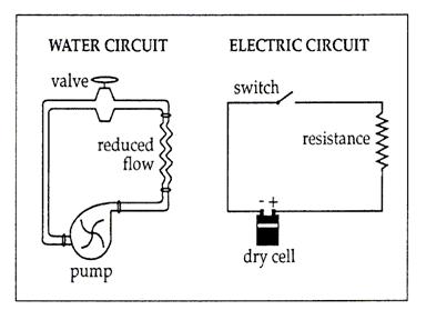
We start with the three basic parts of a circuit: a source of voltage (symbol V – measured in volts) that pushes a certain amount of charge past a point in a circuit in a given period of time, known as current (symbol I – measured in amps). This current encounters a device that performs some function (a light-bulb for example) which is known as a resistor (symbol R – measured in Ohms) because it resists the flow of current.
Voltage: the “electric pressure” that IS the electric field which pushes available charges through a circuit – think of it as the amount of energy given to each bit of charge
Current: the amount of charge passing a point in a given period of time
Resistance: something that utilizes the moving charges and generally restricts the amount of current in a circuit
What is the relationship between voltage, current, and resistance?
 The relationship between voltage, current, and resistance in an electrical circuit is fundamental to the operation of any circuit or device. Verbally, the amount of current flowing through a circuit is directly proportional to the applied voltage and inversely proportional to the circuit resistance. By explicit definition, one volt of electrical pressure can push one ampere of current through one ohm of resistance. Two volts can either push one ampere through a resistance of two ohms, or can push two amperes through one ohm. This is known as Ohm’s Law, and is expressed mathematically as:
 |
Any circuit must have a source of voltage (like a battery) and a device (which acts as a resistor) that uses the energy provided by the electric field. The components must be connected with conductors and must be arranged in a loop. There are different ways of arranging the elements in a loop – the two basic ways are in SERIES or in PARALLEL.
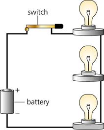
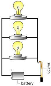
| The circuit below has three light-bulbs wired in series. This means that the current has no choice but to flow through one bulb, than the next, and the next, and so on until it goes to the other side of the battery. | The circuit below has three light-bulbs wired in parallel. This means that the current flows equally through all three bulbs simultaneously, then goes to the other side of the battery. |
 |
 |
The voltage (electrical pressure) drops across a resistor. In a circuit, this means that the voltage is higher on one side of a resistor than the other. In effect, the resistor takes up some of the electrical energy available in the electrical field (remember the voltage IS the electrical field!) in order to perform its function (such as providing light or turning a motor).
With a battery of a certain voltage, the bulbs in a series circuit are dimmer than they would be if wired in parallel. This is because there is much less current in the circuit. Each light bulb restricts the flow of charges, and their effects are additive, resulting in a small current.
When wired in parallel with the same battery, the bulbs are brighter, because each bulb has its own direct path to the battery, so the charges never need to flow through more than one bulb before they get back to the battery.
This leads us to some generalizations about series and parallel circuits:
Series Circuits:
 The total voltage drops across all the resistors is simply the sum of each individual voltage drop, and this sum is equal to the voltage supply of the battery. Therefore, the total voltage across ALL the devices (including the battery) in the circuit is ZERO. Why? Because across the battery you have a voltage field that is exactly used up by the resistors in the circuit. Another way to think about this is that the voltage supplied by the battery exactly equals the amount of voltage drops in the circuit, so the TOTAL voltage is zero. Numerically, VT = V1+ V2 + V3 +...+ Vn
- Electric current has but a single pathway through the circuit. This means that the amount of charges passing any given point in the circuit is constant, whether you pick your point in the wire, in a resistor, or even in the battery itself. Numerically, IT = I1 = I2 = I3 =...= In
- This current is resisted by the resistance of the first device, the resistance of the second device, and so on. This means that the total resistance of the circuit is the sum of the individual resistances along the circuit path. Numerically, this is expressed as: RT = R1+ R2 + R3 +...+ Rn
- The total current in the circuit is numerically equal to the total voltage supplied by the source divided by the total resistance of the circuit. This is just Ohm’s Law ( I = V/R )
- Ohm’s Law also applies separately to each device. The voltage drop across each device is proportional to its resistance. This follows from the fact that more energy is used to move a unit of charge through a large resistor than through a small resistor.
Parallel Circuits:
 Each resistor or device connects directly to the battery or voltage source. This means that the voltage across each resistor is the same as every other.
Numerically, VT = V1 = V2 = V3 =...= Vn
- Electric current has many pathways through the circuit. The total current in the circuit divides among the parallel branches. Since the voltage across each branch is the same, the amount of current in each branch is inversely proportional to the resistance of the branch – Ohm’s Law applies separately to each branch.
- The total current in the circuit equals the sum of the currents in its parallel branches.
Numerically, IT = I1 + I2 + I3 +...+ In
- As the number of parallel branches is increased, the overall resistance of the circuit is decreased (because the charges have more paths to follow). Overall resistance is lowered with each added path between any two points of the circuit. This means that the overall resistance of the circuit is less than the resistance of any one of its branches. Numerically, this is expressed as:
